

Enerdrive - Driving Your Energy Needs
Enerdrive - Driving Your Energy Needs - Suppliers of AC and DC-DC battery chargers, inverters, solar panels and controllers, lithium battery systems, Blue Sea products, battery protection and power distribution equipment (from https://www.enerdrive.com.au)
In this article, we will cover specific products, their use and some tech tips.

Enerdrive supply quality independent power products
After 30 years in the business of AC and DC electrics and a lifetime of familiarity using these products, we choose Enerdrive products because of its performance, reliability and back-up service.
Enerdrive's experience in the mobile and independent power market has influenced their product range and they guarantee their products are proven to be reliable, safe and easy to use. They back this up with unrivaled support to all customers who have purchased a genuine Enerdrive product from Keogh's Marine and RV or other dealers.
Power for caravans, boats, 4wd’s and even off-grid solutions in remote outback areas, Enerdrive has the independent or mobile power appliance and power system accessories to suit your application. Enerdrive's new range of compact lithium batteries and lithium system solutions are ideal for caravans and RV’s venturing out to remote areas of Australia.
For an in-depth look at Enerdrive products, choose a product category from the Category menu.
Understanding Pure Sine Power Inverters (Sep 19, 2016)
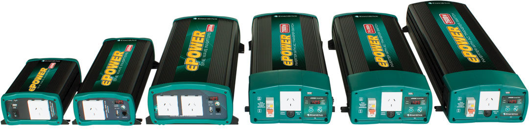
An inverter is a piece of equipment that converts DC battery power into AC 230v mains power. Inverters are available in varying wattage outputs ranging from 150w through to 5000w+.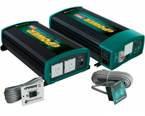
When inverters were first invented, they produced what is called a "Modified" sine wave output. This AC power output back then was suitable for all types of appliances, but as timed moved forward, and electrical appliances became more sophisticated, the old modified sine wave inverter was just not up to speed to cope with modern electronics, hence the invention of the "Pure" sine wave unit.
Today, just about every AC powered appliance with sensitive electronics requires a pure sine inverter to operate correctly. They are designed to precisely replicate and even improve on the quality of electricity supplied by utility companies. There is generally no compatibility issues with any appliance run from a pure sine wave power inverter.
The major key to having a successful inverter setup is how you cable the DC feed to the inverter. Many issues we see with inverters is due to "under cabling" the input to the inverter. As the inverter AC output increases, so does the flow of current coming from the battery. The DC voltage however reduces as you put more load on the inverter. If the cable size is too small, the inverter won’t be able to reach its maximum output due to the DC voltage dropping below the shutdown voltage of the inverter. If the voltage drops more than 0.25V from the battery to the inverter, a significant decrease in inverter performance will occur – and the inverter will not perform well.
For your inverter to perform, you must make sure you feed it correctly. The right size DC input cables will help do this. Sizing the correct input cables is a critical requirement for maximum performance from your inverter. An inverter operates best if installed less than 1.5meters from the battery source.
Below is a chart with the correct DC cable size required for the Enerdrive ePOWER inverter range and pretty much most inverters of the same capacity on the market today.
|
Part No |
Size |
mm² ≤1.5m |
|
EN1104s |
400w |
10mm |
|
EN1110s |
1000w |
35mm |
|
EN1120s/x |
2000w |
70mm |
|
EN1120x-24v |
2000w |
50mm |
|
EN1126x |
2600w |
95mm |
Proper installation is primarily a matter of sizing a cable to match its task, using the correct tools to attach terminals, and providing 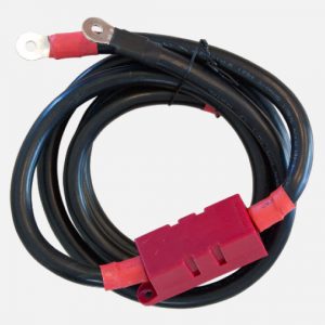 adequate over-current protection with fuses and circuit breakers.
Many people get confused about measuring cable. Cable sizing is simple enough. It is a function of the length of a cable (measuring from the power source to the appliance and back), and the current (amperage) that will flow through it. This can be found by checking the label on the appliance in the circuit, or the specifications sheet for the appliance. The longer the cable, or the higher the amperage, the bigger the cable must be to avoid unacceptable voltage losses. And there should always be plenty of extra margin for safety because an appliance may actually use more current than what it is rated for because of heat, low voltage, extra load and other factors.
New ePOWER Inverter with AC Transfer Safety Switch Protection
There is an old saying, "Why build a better Mouse Trap". If it works and does the job, why do you need to go out of your way, spend time and resources to make it better?
Well at Enerdrive we were stuck with this idea for a very long time when it came to installing Power Inverters into applications such as caravans and boats. You see in permanent installed inverter applications there is a need for an inbuilt Automatic AC transfer switch to allow the on-board power points to be active when away from a mains power supply – common sense and a blessing for a customer who has made the investment for an on-board Power Inverter.
But In-built Automatic AC Transfer switches require hardwired AC connections, and hardwired AC connections require the use of a licenced 240vac electrician to work on. This is OK at a factory level where there would be a licenced sparky contracted or on staff – but what happens to the end customer IF they have a problem somewhere out and about and the inverter needs to be sent off for repair???
If you don’t know the first thing about AC electrical wiring, this becomes a serious safety hazard and can become a nightmare to resolve for both Enerdrive, and our customers. And from almost 20 years of experience selling AC hardwired Power Inverters we can tell you first hand the heartache of this occurrence from all parts of this big country.
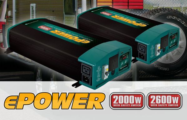
So what’s the solution?? – you need to make your inverter AC Transfer switch a complete ‘Plug and Go’ system. And in ‘making a better Mouse Trap’ Enerdrive are please to introduce our all New ePOWER Pure Sine Wave Inverters with AC transfer switch using 16amp IEC power plugs for mains in and out. These inverters are available in Two new 12v models at 2000w 2600w plus the new 2000w/24v model, all with built in serviceable RCD.
Even better still, is that we have now included integral to the inverter the AS/NZ 4763 Australian Compliance required Type ‘A’ RCD Safety switch to protect all outputs while in Inverter mode.
From a service perspective – If you ever need to remove the inverter, the actual customer can now simply pull out the inlet and outlet plug by hand – push them together and their circuit is complete for use while on AC mains powered sites (no AC sparky is required at all, no additional costs involved in servicing).
We at Enerdrive believe that this is possibly the most superior advancement in Pure Sine Wave Power inverters in many years, and puts the ePOWER inverter range at the forefront of the Australian market.
How To Correctly Connect Deep Cycle Batteries And Choose The Right Cable Sizing
There are several ways to wire multiple batteries to achieve the correct battery voltage or capacity for a particular DC installation. By connecting batteries in series or parallel or both as one big bank, rather than having individual banks will make your power source more efficient and will ensue maximum service life for your battery bank.
|
|
|
|
|
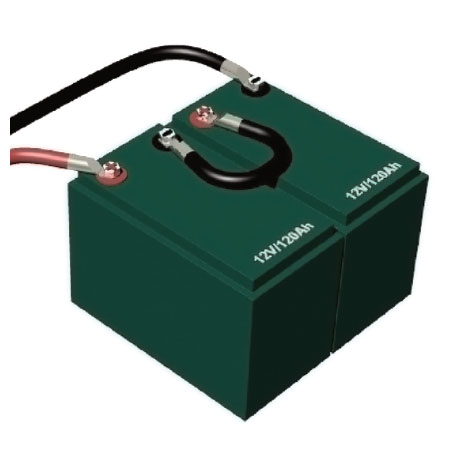
Series Connection Wiring batteries together in series will increase the voltage while keeping the amp hour capacity the same. For example;
|
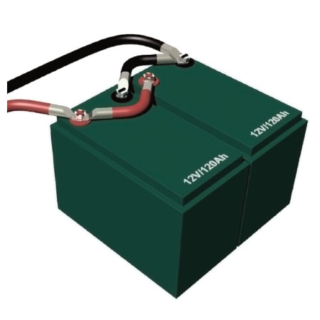
Parallel Connection Wiring batteries together in parallel has the effect of doubling capacity while keeping the voltage the same. For example;
|
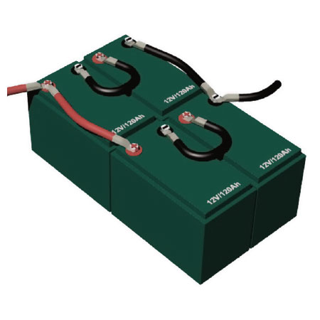
Series/Parallel Connection This is a combination of the above methods and is used for 2V, 6V or 12V batteries to achieve both a higher system voltage and capacity. For example;
|
Battery Cable Connections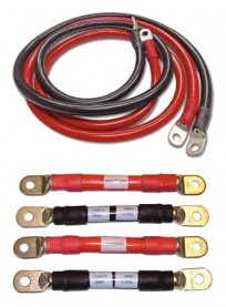
The cables that join your batteries together play an important part in the performance of your battery bank. Choosing the correct size (diameter) and length of cable is important for overall efficiency. Cables that are too small or unnecessarily long will result in power loss and increased resistance.
When connecting batteries in series or parallel or series/parallel the cables between each battery should be of equal length. As you can see in the diagrams above, all the short cables connecting the batteries together are the same length and all the long cables are the same length. This links the batteries together with the same amount of cable resistance, ensuring that all batteries in the system are working equally together.
Particular attention should also be paid to where the main system cables are connected to the battery bank. More often than not, the system cables supplying the loads are connected to the first or "easiest" battery to get to in the bank, resulting in poor performance and service life. These main system cables that run to your DC distribution (loads) should be connected across the whole bank as illustrated in the diagrams to the left. This ensures the whole battery bank is charged and discharged equally, providing optimal performance.
The main system cables and the cables joining the batteries together should be of sufficient size (diameter) to handle the total system current. If you have a large battery charger or inverter you want to make sure that the cables are capable of carrying the potentially large currents that are generated or consumed by these pieces of equipment, as well as all your other loads.
Series Connection -Batteries are coupled in series to gain higher voltage, for instance 24 or even 48 Volt. The plus pole of each battery is connected to the minus pole of the following one, with the minus pole of the first battery and plus pole of the last battery connected to the system. This type of arrangement shown is a 24v, 120Ah bank.
Parallel Connection -Parallel coupling involves connecting the plus poles of multiple batteries to each other and the same with the minus poles. The plus of the first battery and the minus of the last battery are then connected to the system. This type of arrangement is used to increase capacity (in this case 12v 240Ah).
Series/Parallel Connection -A combination of series and parallel connections is required if you need for example a 24 Volt battery set with a higher capacity. The battery should then be cross-wired to the system using the plus pole of the first and minus pole of the last battery. This type of arrangement shown is a 24v, 240Ah bank.
Cable Sizing -In an independent power system, you generally would find an inverter and battery charger system working for the common goal of providing power. What ties each of these together are the cables to supply the power to run to or from the batteries or DC distribution. Unfortunately, the most common installation error is to under-size cables to the load/s or from the recharge sources.
Proper installation is primarily a matter of sizing a cable to match its task, using the correct tools to attach terminals, and providing adequate over-current protection with fuses and circuit breakers.
Cable sizing is simple enough. It is a function of the length of a cable (measuring from the power source to the appliance and back), and the current (amperage) that will flow through it. This can be found by checking the label on the appliance in the circuit, or the specifications sheet for the appliance. The longer the cable, or the higher the amperage, the bigger the cable must be to avoid unacceptable voltage losses. And there should always be plenty of extra margin for safety because an appliance may actually use more current than what it is rated for because of heat, low voltage, extra load and other factors.
For 12V circuits, the relationship between cable length, current flow, and cable size is given in the table below. Note that you have two circuit types, Critical Non Critical. The "critical" circuit is based on a 3% voltage loss in the cable, while the "non-critical" circuit is based on a 10% voltage loss. What this means is that when the circuit is fully loaded (i.e. operating at rated amperage), the voltage at the appliance will be 3% or 10% below that at the battery. For example, if the battery is at 12.6 volts, the appliance will be seeing 12.2 volts (3% loss), or 11.34 volts (10% loss).
Many appliances (notably lights) will run fine with a 10% voltage loss, but others are particularly sensitive to such losses (notably charging circuits, and some electric motors). In general, given the harsh realities of the RV marine environment, it’s better to use the 3% volt drop table when sizing cables, rather than the 10% table. There’s never a performance penalty if a cable is marginally oversized; there is always a performance penalty (and possibly a safety hazard) if it’s undersized.
The ground (negative) cable is as much a part of a circuit as the positive cable; it must be sized the same. In general, each appliance should be supplied from the distribution panel with its own positive and negative cables, although lighting circuits sometimes use common supply and ground cables to feed a number of lights (in which case the supply cables must be sized for the total load of all the lights).
For 24v systems, the cables size is half that of a 12v setup.
Always read product recommendations, or check with your supplier to know and understand exactly what size cable is required for your products.
A detailed cable sizing chart is listed on the page 7. The cable sizing table is used by running across the top row until the column with the relevant amperage is found, and then moving down the left-hand column until the row with the relevant distance is reached. The colour coding in the body of the table at the intersection of this row and column is the wire size. Compare this with the Cable Conversion Table to see what size cable to use.
The AWG (American Wire Gauge) is used as a standard method of denoting wire diameter, measuring the diameter of the conductor (the bare wire) with the insulation removed. AWG is sometimes also known as Brown and Sharpe (BS) Wire Gauge. Most Australian Auto Electricians use the BS scale.
Also listed is a conversion chart from AWG/BS to mm². This table gives the closest equivalent size cross references between metric and American wire sizes. In Europe and Australia, wire sizes are expressed in cross sectional area in mm².
Other important points to bear in mind when wiring boats or RV’s:
- All circuits should be as high as possible with no connections in or near bilge water or damp areas.
- All cable lug connections should be well crimped and NOT soldered
- It is preferable to use tinned cable where possible in a marine environment
- Use twisted-pair cable for any wiring within 1m of a compass.
- Never tap into existing circuits when installing new equipment; run a properly-sized new duplex cable (positive and negative cable in a common sheath) from the distribution panel (or a source of power) to the appliance.
- It is recommended to label all cables at both ends, and you should keep an updated wiring plan on board, to aid in future troubleshooting.
- Each circuit should have an independent ground cable, and all the ground cables should eventually be tied back to a common ground point/bus bar which is grounded to the battery negative; if devastating stray current is to be avoided, this is the only point at which the grounds should be interconnected.
- Unless in a conduit, cables should be supported at least every 450mm.
- Although black is often used for DC negative, it is also used for the live wire in AC circuits in the USA. That means there is potential for dangerous confusion. DC and AC wiring should be kept separate; if they have to be run in the same bundle, one or the other should be in a sheath to maintain separation and ensure safety.
- Be sure to isolate the batteries before working on the DC system, and, for safety sake, shut off all potential AC power sources (the shore power, and on-board AC generator, or an inverter)
Recharge Your Entire Battery System with the ePOWER Battery Charger
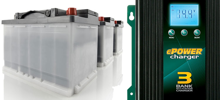
Recharging multiple batteries has never been easier.
Bank 1 PRIORITY – Charge Where You Need it Most
The ePOWER Charger delivers a priority charge to Bank 1, or your main house battery bank which allows the charger to get this bank recharged the quickest, then transition the cycle to the lesser bank 2 3 batteries. The priority function also allows you to have a battery chemistry different to the other two, such as an AGM battery for house and lead calcium for your start banks. In the event that all 3 banks are in need of a charge, an over-ride function helps recover all 3 banks quickly and evenly before switching back to prioritise on Bank 1.

The Perfect charging solutions for lithium, flooded, AGM or gel batteries.
The Enerdrive ePOWER Battery Charger is a fully automatic, "set and forget" charger - It is designed to quickly and accurately recharge your batteries using algorithms that help maximize service life. Multistage smart charging technology enables the charger to be connected to your battery banks permanently. As dictated by battery manufacturer’s recommendations, batteries require a multistage charge sequence for perfect, fast and accurate charging. Our ePOWER multistage smart chargers deliver four primary charge stages:-
-
Stage 1 – Bulk or Boost Charge; The battery is charged at full rated output current of the charger until the battery reaches its final charging voltage, known as its absorption voltage. In this step, around 80% of the battery capacity is recovered as fast as possible.
-
Stage 2 – Absorption Charge; With the charger voltage held steady the remaining 20% is replaced allowing the current to drop as the battery approaches its full charge.
-
Stage 3 – Float; Finally, in the float stage the charger voltage is lowered and held at a constant and safe predetermined level. This prevents the battery from being overcharged while supporting any additional loads connected to the battery, such as DC lighting and refrigerators. This stage allows for the charger to be used as a DC power supply.
-
Stage 4 – Maintenance; This stage is a regular timed "return to bulk" stage. After 7 days of constant operation in "float" the Enerdrive ePOWER Battery Charger will switch the charger from float to bulk to agitate the batteries electrolyte helping to provide an extended service life.
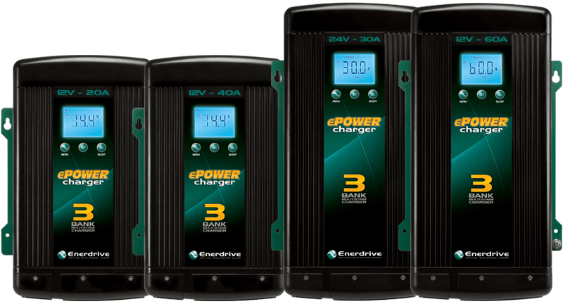
Features
- Multistage Charging: Fully automatic multistage battery charger with the ability to charge 3 separate battery banks
- Separate Battery Banks: Isolated charging design where battery bank one is separate from battery bank two and three
- Programmable: Battery bank 1 can be programmed with a different charge algorithm over banks 2 and 3
- Current Control: User adjustable current output (e.g. Dial the 60amp unit back to run off a 1kVA generator)
- Smart Charging: The ePOWER battery charger will regulate its output based on the loads connected to your battery banks
- Wide AC Input Range: Operates on both 110V / 60Hz and 240V / 50Hz
- LED Display: Easy to use "set and select" menu along with scrolling charger status
- Silent Mode: Disables the cooling fan for total silent operation at night or whenever required. Activation reduces charge output by half and locks out fan for 12 hours
- Temperature Sensor: Battery temperature sensor included with 3 meter cable
- 2 Year Warranty from an Australian company renowned for customer support
The Display Panel
The ePOWER Charger display gives you all the information you need for the operation of your charger. At a glance, key information such as charger amps, battery voltage and charge state continually alternate on the screen. When in float / power supply mode, the load amps are displayed so you can see exactly what the charger is doing. The display also allows you to program all settings of the charger, as well as activate the silent mode.
Silence when you need it – By pressing the "SEL" button for 5 seconds, the ePOWER Charger enters the ‘Silent’ mode that prohibits the fan from working. This ensures totally silent and safe operation at night, ideal if the charger is located close to your sleeping quarters. Silent mode limits current output to no more than 50%, and is programmed to remain on for 12 hours before automatically returning to a normal ‘fan-on full output’ setting.
It’s All About Lithium
The recent advances in high capacity Lithium battery technology have seen the need to develop a battery charger suited to their needs. With most traditional ‘smart’ chargers their suitability to Lithium batteries is limited. Lithium batteries require a constant current / constant voltage charge algorithm and are unique in that almost every amp-hour of charge delivered by the charger is accepted as one amp hour into the battery, hence the need to deliver a constant current as long as possible.
The Enerdrive ePOWER charger can be programmed for Lithium batteries. This setting delivers the full rated output of the charger constantly with the charger switching to power supply mode once the voltage peak is met (indicating a full battery bank). The graph below shows the ePOWER charger algorithm perfectly supporting Lithium battery requirements.
How to Charge a flat battery with an ePOWER charger
Using an ePOWER charger to recover a battery below 3.5vdc - The ePOWER charger is designed to recharge and maintain a deep cycle battery to the best of its capabilities in normal operating conditions. There however is the rare occurrence when a battery may be discharged well below its safe levels and require recharging, of which the ePOWER in normal charge mode needs greater than 3.5 volts DC to activate the Micro Processor to start the charger.
For a conventional 12 volt deep cycle battery to be discharged well below 9vdc can cause numerous issues while recharging, with the greatest risk of a cell collapsing or a thermal runaway event occuring. Discharging a battery past 9vdc will severely shorten the life of the battery, if not cause it to be irrecoverable if voltages reach as low as 1 or even 0VDC.