Enerdrive eLITE Battery Monitor Explained
Tech tips on installing and using the Enerdrive eLITE Battery Monitor - by Andrew Wilson from Enerdrive
We have created this Tech Tip to help people understand the Enerdrive eLITE Battery Monitor from an installation and function point of view.; Over the years, we have had many customers contacting us for help and explanation of how to install the meter correctly, programming it and the general understanding of the information it displays. As the battery monitor is the “fuel gauge” for your battery bank, the installation, setup and displayed information is critical for maximum life and performance of your stored power source.
So here we go;
The Enerdrive eLITE battery monitor shows battery voltage, percentage of charge, amperage amp hours consumed at any given time using the monitors internal software through a shunt on the negative battery terminal while charging or discharging. It does this by using algorithms takes into account Peukert’s equation during the charge discharge cycles.
The eLITE monitor is designed for batteries with capacities from 20 to 999 amp hours and is coupled to a 500 amp shunt.
What is included in the kit:
* Enerdrive eLITE battery monitor
* 500 amp shunt
* Shunt quick connect PCB module
* Monitor quick connect PCB module
* Five metre category 5E UTP patch cord
* Fused positive lead with 10mm diameter terminal with one 10mm diameter ring crimp terminal
* One 10mm diameter ring crimp terminal two crimped spade terminals
* Screwdriver
* Installation instructions
Installing the Enerdrive eLITE:
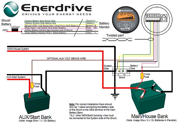
We have recently introduced a new ‘quick connect kit’ for the monitor which includes PCB modules on both the shunt and monitor, allowing for a hassle free connection via a five metre patch cord. There is just one more connection to make with the supplied fused wire between the “main” battery input on the shunt PCB and the positive battery terminal.
ALL negative battery cables (whether it be loads or charging) that you would normally connect to the battery negative are now connected to the “SYSTEM” side of the shunt. The only negative cable connected to the battery is the cable attached to the ”BATTERY” side of the shunt. For the meter to read accurately it needs to see all of the current flowing through the shunt to register the exact condition of the battery. You can also use the eLITE to monitor the voltage of a second battery too, like a vehicles starting battery for example. See illustration and installation information below.
Programming the meter after installation:
Please take the time to read the instructions a few times understand how the monitor works, the parameters it covers the display screen functions.
Once powered up the display will start blinking. Push one of the three buttons the monitor will stop blinking.
Please Note: If you have a meter manufactured from 2014 onwards, please refer to the “r.c Reset zero-offset current” section of the Reset Functions section below before proceeding.
First step is to set a number of parameters of your own battery system into the monitor over the factory preset settings. To do this press the ‘setup’ key for 3 seconds. Use the > and < keys to browse through the different functions, then by pressing the ‘setup’ key again the selected function can be viewed. The ‘ > and < keys can now be used to change the value. Pressing the ‘setup’ key again will return you to the setup menu.
From any menu position, the normal operating mode can be accessed again by pressing the ‘setup’ key for 3 seconds. This will also save any function value changes to the memory. When no keys are pressed for 90 seconds the monitor will return to normal operation mode without saving any function value changes you have made.
Display Control Overview
1. Charge battery indicator
2. Alarm activated indicator
3. Numeric value indicator field
4. Readout units
5. Main battery or auxiliary battery indicator
6. State-of-charge bar
7. Synchronize indicator
8. Select state-of-charge readout or next value
9. Select current A or Amphour Ah readout or enter/leave setup menu
10. Select voltage readout main or auxiliary or previous value
The “F” Functions Explained:
F01 Battery capacity. Change the default 200 amp hour battery capacity for your own. For example, if you have a 120Ah battery, then change the capacity to 120.
F02 Charger’s float voltage. Change the default float voltage to the lowest that your 240v battery charger, DC to DC charger or solar regulator puts out. The default setting is 13.2 volts.
F03 Charger’s float current. The default setting is 2.0%.
F04 Low voltage alarm state-of-charge percentage scale. When the state of charge percentage has fallen below the set value, the alarm will be activated, the charge battery indicator starts flashing the state of charge bar is empty. The default setting is 50%.
WE STRONGLY RECOMMEND LEAVING IT SET TO 50% FOR ALL FLOODED, AGM, GEL BATTERIES
F05 Low battery alarm on. When the battery voltage has fallen below this value, the alarm will be activated. The default setting is 10.5 volts.
F06 Low battery alarm off. When the state of charge percentage has risen above this value the alarm was activated, the alarm will deactivate again. When “FULL” is selected the alarm relay is deactivated when the auto-sync parameters are met. The default setting is 80%.
F07 Peukert’s exponent. The default setting is 1.25. This is suitable for all flooded batteries. For AGM GEL batteries the average figure is between 1.12 – 1.15. Most battery manufactures will have the correct Peukert’s Exponent number listed for their batteries. If unsure, please contact your battery manufacture.
Peukert’s law, presented by the German scientist W. Peukert in 1897, expresses the capacity of a battery in terms of the rate at which it is discharged. As the rate increases, the battery’s available capacity decreases.
F08 Shunt Amp Rating. The default setting is 500 amps.
F09 Backlight mode. You can change the number of seconds the backlight stays lit. The default is 30 seconds. It can be set to always be on or off. “AU” activates the backlight when a key is pressed or automatically when the charge or discharge current exceeds one amp. The backlight draws approx one milliamp.
F10 Alarm contact polarity. The default setting is NO “normally closed”.
F11 Auto-sync sensitivity. This function has a range from 1 to 10 and is used to calculate the percentage of the battery back to 100% via the settings used in F02 F03. If auto sync takes too long or does not occur, lower this value. If battery monitor syncs too early, increase the value. The default setting is 5.
F12 Firmware version. Displays the firmware version of the monitor.
Reset Functions:
The last three functions are so called Reset Functions. The default value for all Reset Functions is “OFF”.
To actually reset the selected Function, use the lt; and gt; keys to change the value from “OFF” to “ON”. Pressing the SETUP key again, will step back to the Setup menu. All reset items set to “ON” will only be reset once the Normal Operating Mode is accessed again by pressing the SETUP key for 3 seconds.
The following Reset Functions are available:
r.b Reset Battery status. Use this reset item to reset your current battery status, for example after you have installed a fresh battery of the same specifications as the previous one.
r.F Reset Functions. This reset item can be used to reset all Function values to factory default values.
r.c Reset zero-offset current. This function is installed in all meters manufactured from 2014 onwards.
Use this reset item to remove small current readings on the display when no current is flowing in or out of the battery. When performing this reset action, please be 100% sure that all DC consumers chargers are disconnected or turned off. A very accurate way to use this function is to disconnect all negative cables from the “SYSTEM” side of the shunt then, perform this action. The meter should then read 0.0A and the meter has then been calibrated specifically to your electrical system.
Synchronization
When the meter is powered up for the first time, the display will show a 100% full reading. This is because the monitor thinks you have connected a brand new battery that is charged to 100%. This also is the case if you disconnect the power to the meter and reconnect it.
Also displayed when you first start the monitor up for the first time is the word “SYNCHRONIZE” which means you need to fully charge the battery so the monitor can familiarise itself with your system settings.
The battery charge is complete when the F02 ; F03 settings are reached for a period of four minutes or more which means it has reached float mode. A flashing “FULL” message will be displayed. The “FULL” message will disappear when any key is pressed or when the battery starts discharging.
During normal operation the monitor will automatically indicate when a synchronize is required by displaying the word “SYNCHRONIZE”. The more often the battery is charged, the more precise the battery monitor will indicate all parameters.
You can also manually sync the monitor with the battery if you know it is full by pressing down both ‘Vlt;‘ ‘%gt;’ keys simultaneously for three seconds.
Explaining the eLITE display screen
Main battery voltage: Will be displayed in the top of the screen by pressing the ‘V’ key. If you are monitoring another battery like the starter of a vehicle, the voltage of that battery can be shown by pressing the ‘Vlt;‘ key again and the little battery symbol will change from “MAIN to “AUX”. pressing the ‘V‘ key again will change it back to the “MAIN” battery.
Battery percentage remaining: Will be displayed in the top of the screen by pressing the ‘%’ key.
Amps: Flowing in or out of the battery will be shown in the top of the screen by pressing the ‘A/Ah’ key. Charging amps are shown followed by ‘A’ while discharged is shown with a minus prefix followed by ‘A’. The result is shown in real time, for example charging from a solar panel may show ‘6A’ while a fridge drawing on the battery may be shown as ‘-3A’. If for example the solar panel is charging the fridge is discharging the battery at the same time, using the above figures the monitor would show ‘3A’. Another example, if the solar panel was charging the battery at ‘1A’ the fridge drawing ‘-3A’, then the monitor would show ‘-2A’.
Amp hours: Are shown in the top of the screen by pressing the ‘A/Ah’ key again. When you are discharging from a full battery the ‘Ah’ will be prefixed by a minus, for example ‘-20Ah’, however when the battery starts to charge the ‘Ah’ reading will count back to zero. For example if the monitor shows ‘-20Ah’ the solar panel produces a steady input of 6amps over an hour then it may show a figure of ‘-14Ah’.
State Of Charge: Is shown as a percentage number and as a bar graph. The bar graph is always showing across the bottom of the screen is a handy quick glance to see what is happening at any time without pressing buttons.
State of charge percentage scale. The state of charge bar graph is shown across the bottom of the screen at all times. This can be set to your own preference to show the graphs lowest percentage level anywhere you wish. The default setting is 50%, that is the graph will show empty when the battery gets to 12.2volts.
Wiring Diagram Using Quick Connect Kit
OR
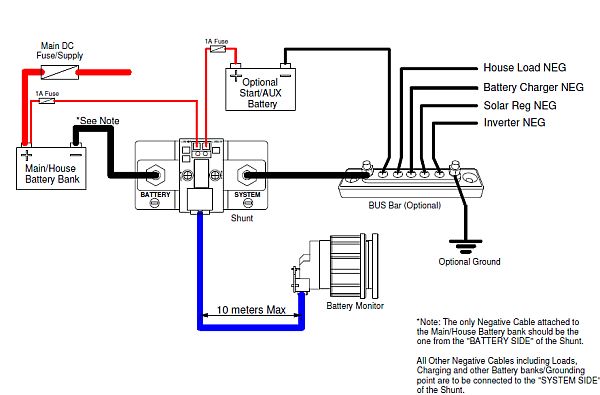
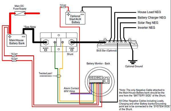
Wiring Diagram - Hardwired
(Recommended For Professional/Commercial Applications)
Battery Monitor Setup