


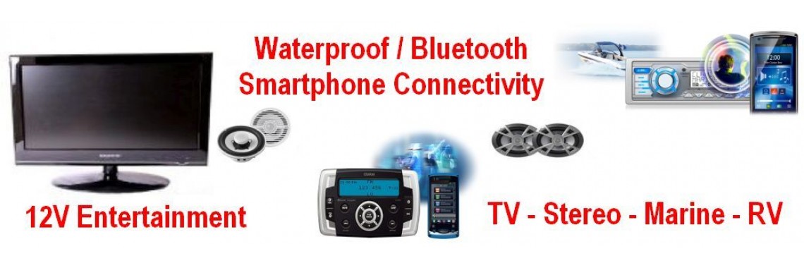


Technical Info - TV Reception
Technical Info - TV Reception
TV Reception:
Why it is such a problem and what you can do about it!
Signal is energy and it travels through the air. It takes quite a journey, which starts at the TV station. Imagine this laser- like piece of energy travelling through the air and bumping into and penetrating objects as it goes. These interferences alter the course and characteristics of the signal as it travels to its destination – your antenna. Depending on its design, the antenna picks this signal up and directs the energy onto your cable. To achieve this, the signal has to travel through various components on the antenna, down the cable through various plugs and sockets, finally arriving at your TV set. The set decodes the signal and presents you with a good picture – we hope!
Generally, consumers expect TV sets to just magically produce good pictures. Bad pictures equal bad TV sets! This is not true. The antenna’s vital function in the process is not recognized. The antenna is the key to you being able to duplicate on your TV set, that which emanated from the TV studio. Sets today are generally capable of providing very good pictures but without the energy (signal) they cannot reproduce the picture.
What stops the picture arriving?
Firstly, there are the constraints caused by the bumps, hills and trees on the earth’s surface. Caravanners generally find themselves under mountains, beside rivers or by the seaside - all locations that suffer with signal problems due to the surrounding earth formations which restrict the flow of signal.
There is a second constraint - the mobile Caravanner wants to be able to pick up a variety of channels. He is not based in a single location like the homeowner, who installs his antenna for a known, set number of channels. This means his antenna is peaked for the channels he seeks. From a technical point of view, it is quite an easy task to design an antenna for a known set of channels, even when signal conditions are difficult. However for the mobile Caravanner, this is not the case. His antenna must work for every channel and must be flexible enough to work in every type of location. Technically this is an impossible ask. There is not an antenna made yet that works on every channel (frequency), mounted vertically or horizontally, that can perform under all conditions and deliver good quality pictures.
So how does the Caravanner handle this! I am told that TV reception is the second most talked about subject in a Caravan Park, after the weather. In my experience (about 30 year’s worth), Caravanners purchase 4 or 5 antennae before they finally get it right. This number has been quoted to me on very many occasions.
There are a few other important points. Approximately 2500 transmitters are now operating around this wonderful continent. Of these, approximately 2100 are on UHF, “Ultra High Frequency”. This frequency range is represented by the numbers 28 to 69 as opposed to “VHF - Very High Frequency”, which is represented by the numbers 0 to 12. This is an important concept to understand if you are to make the right decision when buying your caravan antenna. It is very important that the product Caravanners buy is efficient on UHF as UHF represents 75% of their opportunity to receive signal.
What is signal?
Signal is energy and every piece of energy has a waveform. Remember when you were a kid and you shook the hose and it wriggled? The hose went up and down like a camel’s hump. The energy you put into the shake created lots of these humps or just a few that lasted only seconds. Well, that is how the wave looks when it travels through the air. Every channel frequency (represented by a number) has a unique wave. The VHF waves are much longer than the UHF waves. That is why you have little elements (lengths of metal or plastic) for UHF and long elements for VHF. They each do a job. Now we need to break this down a little more to make the concept clear. VHF is represented by waves approximately 4’ to 20’ in length. That is quite some difference. Imagine catching things 4’ long and then with the same arms catching things 20’ long. UHF on the other hand has waves that are approximately 15” to 2’, not quite the same problem. If you can manage 2’, the chances are you can manage 15”. Each variation of length represents a change in frequency and channel, which translates to a number. So the slightest adjustment to an antenna element can make a big difference to an antenna’s potential to pick up the energy. The length of the wave matches the length of the element.
Now look at different antennae. You will see some with short elements and long elements in some sort of combination. You will see plastic elements that are quite long; you will see every imaginable combination if you have a good look. What are all these different things doing? Well they are trying to capture a combination of waves that go from 15” to 20’ and some antenna manufacturers would have us believe that these antennae can do this effectively and equally as well on each channel (frequency) number. Well that is not true. If you look at antennae with this little bit of knowledge under your belt, you will see some are more suited to certain channels than others.
The solution……………….
Explorer Caravan Reception Systems have taken all of this knowledge into consideration before coming up with the best possible caravan antenna system. Firstly, we decided the antenna had to work well on UHF as 75% of available channels reside there. Having a background in TV reception, the designers knew something would have to be compromised, so they chose the very low channels, those with long elements like 0, 1, 2, 3, & 4. Channels 3 & 4 are rare today as they are used for FM reception and channels 0 & 1 are only used in a couple of places; channel 2 is restricted generally to the capital cities so less than 5% of the available channels reside in this part of the spectrum. These were the obvious frequencies (channels) to compromise. (Note: Channel 2 is retransmitted in most locations on a UHF frequency, which means a number from 28 to 69. Do not associate numbers with programs. When you travel around, the same program can reside on all different numbers, (channel frequency) depending where you are.)
Maximizing the Explorer’s performance on UHF facilitated the opportunity to keep our antenna small with no special attention on the 20’ waves. Because the caravan is a mobile reception point, signal varies from very strong to very weak. Therefore, a booster was designed into the antenna itself. Having the booster in the antenna increases efficiency because the booster is closer to the receipt point of the signal, a big plus point for the mobile Caravanner. The result is a compact antenna, which delivers great pictures on UHF, excellent results on channels 6 - 11 (VHF) and, surprise, surprise! It even performs on the long waves channels 0, 1 & 2 in good signal areas.
Thirty years’ experience solving signal problems in town and country lead us to identify the remaining obstacle – cable and connections. There is a massive range of cable on the market. A quick survey revealed low cost, convenient cables were commonly used. Though they performed quite well on VHF, they were very poor performers in the UHF range. This worked against the Caravanner. Manufacturers tended to use these cables out of blissful ignorance so a decision was taken that we would supply all cables and fittings to totally bypass any existing cable and connection system in the caravan. As a result of this decision, the “Thru the wall connection kit” was developed. This kit bypasses any existing wiring in the van and puts in place the Australian Standard in connections, the “F” connector. This connection kit marries the outside cable connection to the inside cable connection all without the use of cable. To reduce connections and cables even further, we incorporated the power injector, needed to power the booster in the antenna, into the same kit.
There is one final point about reception: there are two polarities - vertical and horizontal. This means waves can travels horizontally or vertically and the way they travel is dictated by the Television Station. This is done so we can squeeze more available channels into the spectrum without them interfering with each other. This is important for the Caravanner to understand as he must know when to mount his antenna vertically and when to mount it horizontally. To make life really difficult, there are many locations where the UHF is one way and the VHF is the other. In our Explorer Caravan Reception System kit we provide not only the piece of hardware to make this easy but a book which serves as a guide as to what orientation to use.
All additional accessory items, like an instruction manual, 3 years warranty and money back guarantee were added to the kit to make it complete. It has been designed to totally bypass anything existing that the Caravanner might have. The reason? We needed to know that everything was integrated and would work together to provide the best possible reception under all circumstances. We do not claim that it will work 100% of times but we know that it works 95% of the time and that is a stunning result for a piece of technical equipment that is usually designed for a few channels (frequencies). Get the picture!!!!!!!!
How should I care for and store my antenna system when I am not travelling?
Firstly the telescopic elements can and should be regularly cleaned and protected with a light spray of WD40.
You do this by:
- Extend the arms.
- Using methylated spirits and a worn Scotch brite from the kitchen - clean the elements from the root out to the Tip. This usually removes all salt deposits rapidly and effectively. Allow to dry.
- Spray the elements with WD40 or spray a rag or paper towel and wipe the elements from the root out to the tip.
- Fold in the telescopic elements.
Simply store the antenna away in a protective box (the original antenna box is ideal for storage) making sure of the following:
- That the antenna and antenna components are dry.
- That the cables are not wound too tight or kinked.
- That the weather stopper is fitted to the outside of the connection kit – this must be done every time you disconnect the antenna to insure continued high performance. If you allow moisture into the outside of the connection kit and any corrosion forms then high frequency performance will be highly compromised. For this reason the weather stopper is provided and must be fitted.
Spray the U-Bolt, V-Block and wing nuts of the vertical mount if needed with WD40 and pack in the box.
Store closed box in the van or in some dry protected area.
If you have a mast and mounting then it is advised to also corrosion protect the threaded bolts and nuts used in these with a spray of WD40. If excessive corrosion is noted due to long exposure to salt water or salt air then you can order replacement parts from us. This way you will be ready for your next trip without any hassles.
If your antenna is getting a bit too old then the performance may start to deteriorate and the unit will need repair/service. You can send your antenna system to ‘explorer RV reception systems’ to have this done to return your unit to its original working condition.
Old cables can be very deceptive as they may appear to be fine and yet drop the signal strength by more than 20 db and we have seen as much as 30db drops. And of course caravan antenna cables, unlike in a house, are constantly wound up and put away, stepped on etc. So replacing the cable every so often especially if it appears kinked or corroded or damaged is very important.
Can I drive with the Explorer antenna mounted?
Our answer to this one is generally a big ‘No’. The antenna was not designed to be subjected to wind speeds of up to a 100 kilometres per hour for extended periods of time. The C3 antenna in particular with its telescopic elements would not be suitable for these wind speeds. All antennas are designed for wind gust loads of course but that is different from a prolonged exposure that driving would cause.
The only exception to this is when the antenna can be lowered into the lee of the caravan bulk itself to be protected from the airflow. This has been done successfully. Such a case is when the mount is on the back of the motor home or van and the antenna is lowered down behind the caravan to be protected by the caravan itself.
Also when the antenna is lowered between the rear of the car and the front of the van and turned sideways so that the airflow hits the ends of the telescopic elements the unit can be protected from the airflow. In short while we cannot recommend this as standard practice it has been done successfully with common sense precautions and an installation that allows the antenna to be lowered into an area of protection.
While driving there can also be other obstructions for the antenna besides wind currents. There are also things like low overhanging tree branches, low bridges, low power cables etc. which could potentially damage the antenna. Also a sudden jolt or braking of the van could dislodge the antenna from its mount and throw it to the ground where it can be badly damaged beyond repair. Strange as it may sound we have had an Explorer antenna sent in for repair which had been thrown to the ground and then run over by the van and crushed and badly mangled. We have also heard of cases where the antenna has been stolen from the top of the van when it has been left on its mount.
So it is a good idea to always store the antenna away in its protective box while driving or when not in use. The few minutes it takes to store it away could save you many hours of grief and expensive repair costs.
Will VHF (Very High Frequency) elements still be needed in the future?
The VHF elements on the ‘explorer C3’ are the telescopic elements. On the ‘explorer C2’ the VHF is the rear antenna that consists of 6 elements.
In the past there were a lot more VHF signals than are present currently. Over the years as new transmitters were installed the percentage of transmitters being UHF have greatly exceeded than that of the VHF.
Currently around 87% of the transmitters around Australia are UHF (Ultra high Frequency) the remaining are VHF. With the addition of digital services around Australia these percentages will remain somewhat the same. The older areas such as the capital cities will remain VHF even when the analogue signals are switched off. A decision by the government was made, I guess, to not force every one to change their existing antennas and so they squeezed the digital signals in between the old analogue signals thus maintaining the VHF range for television. Therefore the answer to the above question is ‘Yes’. At this stage VHF will still be required for some areas and therefore as the caravanners are always on the move they should have an antenna that functions in both areas of the spectrum.
There are no products to list in this category.